How to use AktivFilter 3.4 design software
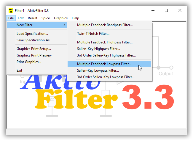
You always start a new filter design with the menu item File - New filter. In the next submenu you select filter type and structure. In this example a Multiple Feedback Lowpass Filter is chosen.
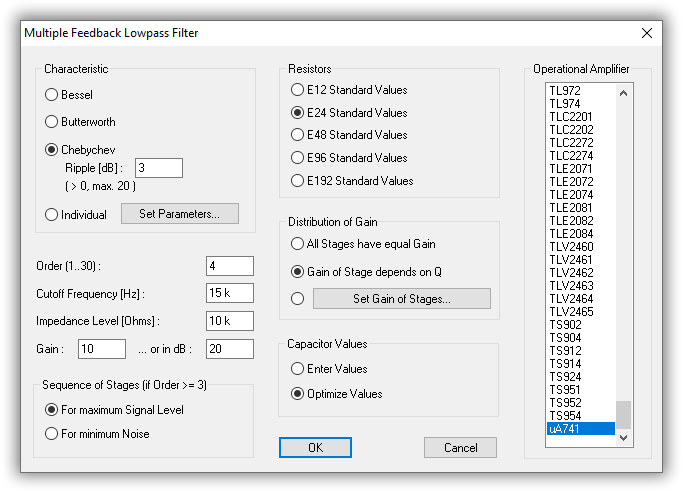
In this dialog you specify all data of your filter.
The field "Distribution of Gain" is a special feature of AktivFilter 3.4: When building a filter, consisting of two or more stages, you can choose how the gain is distributed over the stages. "All Stages have Equal Gain" is the setting similar to the older versions of AktivFilter. However the best choice is "Gain of Stage depends on Q". This means that stages with a higher Q should deliver a lower gain and vice versa. The effect of this choice is that the gain-bandwidth-product of a real opamp has a much lower impact on the result. According to our information, AktivFilter 3.4 is the only available software which has this feature. With the third choice you are able to set the gain for each stage individually.
The calculation of your filter starts with clicking on "OK". During the calculation of your filter a progress display shows the calculation progress in % for each filter stage (not shown here). Thus you can estimate how long you must wait for the desired result.
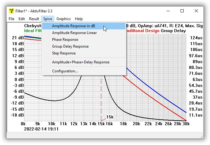
After finishing the calculation, AktivFilter shows immediately a diagram with the amplitude response of your filter:
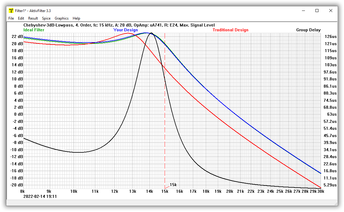
In this diagram, the green curve represents the amplitude frequency response of an ideal filter, that is a filter with an ideal opamp and continuous component values.
The blue curve shows the amplitude response of your design, which considers the chosen opamp type and the standard values of the resistances and capacitors. As you can see, the green curve is covered almost completely by the blue curve. Thus AktivFilter 3.4 has adjusted your design very well.
The red curve (traditional design) shows the amplitude response your filter would have, if you had develloped a filter according to the conventional method, which proceeds from an ideal opamp. As you can see, the result of the traditional design is useless here. Please remember: the designed filter is a Chebychev lowpass 4th-order with a cutoff-frequency of 15 kHz with the opamp uA741. Although these are no unusual requirements you can see the necessity of a program like AktivFilter 3.4.
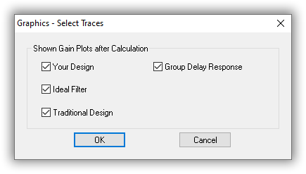
The black curve shows the group delay response of your filter. This is a new feature in AktivFilter 3.4. If you do not see the black curve and want to see it, you can enable it in the dialog Graphics, Select Traces:
In order to display the component values please click on Result, Component values.
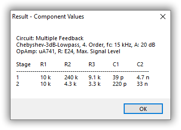
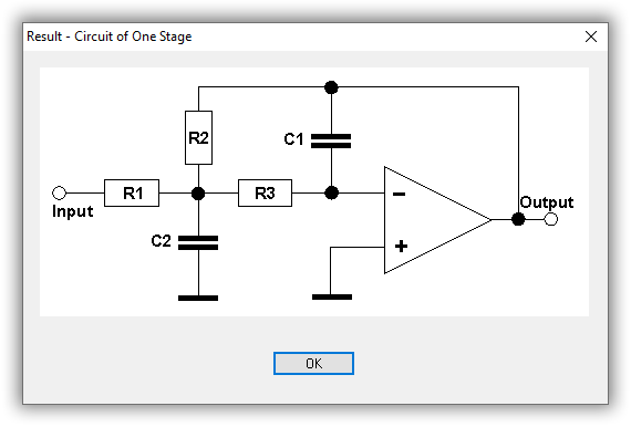
As you can see, all component values are of the E24 standard series. You should also dedicate a view to the circuit diagram. Click on Result, Circuit to see the circuit diagram of one filter stage:
For saving your design to a file you just have to click on Result, Save As. AktivFilter always saves your design to a HTML file with an included picture of the circuit. The picture is saved as a PNG file in the same directory as the HTML file and it has the same filename except the filename extension. Please note that you need both files if you want to distribute your design - e.g. in an Intranet, in the Internet or on a disk. Here you can see the HTML file of the 4th-order Chebychev lowpass which was calculated above.
Perhaps you do not trust the astonishing results of AktivFilter. But that is no problem, because it is easy for you to check any design with the help of Spice, e.g. PSpice or LTspice. Therefore AktivFilter contains an easy to use Spice call interface.
Some remarks concerning PSpice: It does not matter whether you have installed a free version or a full version of PSpice on your computer. If you do not possess a PSpice version, you can download a free PSpice student edition or the free ORCAD lite edition from the ORCAD website (www.orcad.com) or buy the PSpice book by Robert Heinemann. Compared to the full version the free student edition of PSpice has some restrictions, which you should know when using AktivFilter's PSpice interface: The PSpice student edition is able to simulate only circuits with maximum 3 opamps and the distributed libraries contain only the opamp types uA741 and LF411. But there is a solution for the last item: If you plan to use another opamp type you just need a PSpice library file (LIB File), which contains the model of your opamp type. For almost any opamp type supported by AktivFilter 3.4 you can download free of charge such libraries from the websites of the semiconductor manufacturers.
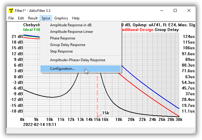
The first time you want to use AktivFilter's Spice call interface you must configure it. Please click on Spice, Configuration:
In this dialog you must specify your Spice configuration:
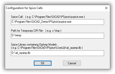
Please fill in the complete path and file name of the Spice version installed on your computer in the upper field.
Please fill in a directory where AktivFilter 3.4 can store temporary files needed for the Spice call in the middle field. These are two files: a file containing the network list (*.CIR) and a file for the control of PROBE (*.PRB). The directory must exist and you need to have the right to create files in it.
Please fill in the name of a library file which contains your opamp models in the lower field. If you are using the free PSpice student edition the library file eval.lib enables you to simulate filters with the opamps uA741 and LF411. If you have created your own library file with opamp models e.g. you have downloaded from the websites of semiconductor manufacturers you can fill in the name of this file here. Please do not forget to copy this file to the path where the other PSpice libraries are stored. In this example I use a library which contains a Spice model of uA741 opamp.
If your settings are complete please click on OK. Your settings are restored any time you start AktivFilter. Your settings are stored in the registry of the Windows operating system under HKEY_CURRENT_USER\Software\SoftwareDidaktik\AktivFilter. Now you can use the Spice call interface. Please click on Spice, Amplitude response in dB:
If your PSpice configuration is set correctly, you will see Spice (in this example PSpice) now:
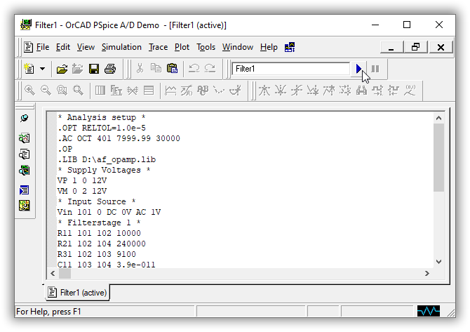
As you can see the PSpice window contains the netlist of your filter. Please click on the small blue arrow, which is at the PSpice window top margin on the right beside the file name, in order to start the simulation (you can also choose "Simulation - Run" from the menu in PSpice).
After having finished the simulation PSpice automatically starts PROBE and presents the result:
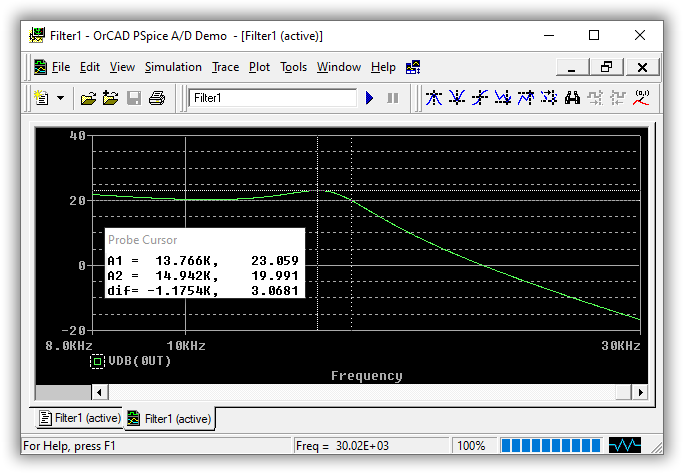
In PROBE you can switch on PROBE's cursor for inspecting the result. As you can see, the specification is nearly perfectly fullfilled by this design. The astonishing good result created by AktivFilter 3.4 is confirmed by PSpice. Now you can switch on your soldering iron to build a prototype of your filter.
A collection of analog filter circuits contains some more filter circuits which were created using the previous version AktivFilter 3.2.
© Circuit Experts 2026
Imprint
· Privacy Policy
· Deutsch